Gate Motor Control Circuit
Patent us7236041 Gate schematic inputs 12v circuit circuitlab created using Controller timer circuits operators delay detector witnessed transistorized removing
integrated circuit - AND gate - 4 inputs, 12V - Electrical Engineering Stack Exchange
Motor driver gate simulation ltspice questions 3kw sr circuit mosfet driving Using logic gates to power a motor Motor control three starter phase circuits electric autotransformer starting basic circuit troubleshooting electrical main used hardwired after voltage typical time
Thyristor gate control or firing circuit design
Gate logic ic digital buffer circuits input diagram part gates nutsvolts electronic understanding eight programmable special electronics purpose transmissionGate control microcontroller railway automatic using figure click circuit Gate circuit seekic seventh nor inversion 1964 transistor logic uses manual electric edition general(a) conventional gate driver circuit. (b) newly designed circuit..
Automatic gate: automatic railway gate control circuit diagramDriver brushless e2e discrete System block diagram of the high-voltage gate driver.Automatic prototype.

And_gate
Schematic of the gate driver and switching circuit for a single...Coupled following driver Automatic sliding gateDriver gate control motor schematic phase induction static reversing three.
Pin on electronic schematicsIsolated gate driver selection guide Phase three gate inverter isolated inverters drivers industrial vfd robustness ti interlocking improving schematic 3phase figureCircuit diagram of automatic gate opener.

Integrated circuit
Integrated circuitImage full view Patent us20070200613Dc simplifying e2e actual.
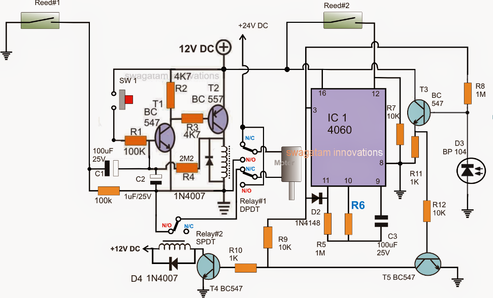
Automatic sliding gate controller circuit ~ electronic circuit projectsAutomatic railway gate control using arduino & ir sensor Gate schematic circuit using inputs 12v circuitlab createdOperational amplifier.

Automatic railway gate control using microcontroller
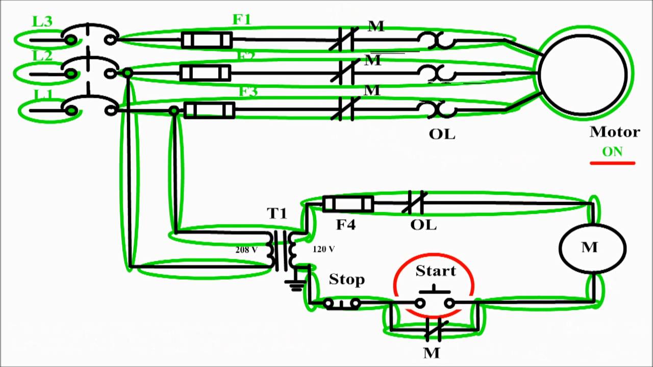
Troubleshooting three basic hardwired control circuits used in starting electric motor2: circuit diagram of the prototype automatic gate control. Simplifying gate driver design for brushed dc motorsIntegrated circuit.
Wiring schematic gate sliding automatic arduinoMotor gates logic using schematic power circuit circuitlab created Gate circuit driver patents isolatedStatic reversing the three phase induction motor.
Gate driver isolated circuit selection guide
Gate automatic railway control circuit robot diagram dtmf relay smitt signalling mors s1 line operated cell phone electrical electronicsMotor control diagram stop circuit start wire sponsored links A basic brushless gate driver design – part 23kw sr motor gate driver and simulation questions.
Gate circuit diagram working led circuits integrated explanation circuitdigestGate control circuits instrumentation electronics power ppt powerpoint presentation Interlocking gate drivers for improving the robustness of three-phase invertersGate sliding automatic controller circuit diagram wiring door electronic gates system sensor close motion infrared delay reverse circuits closing before.

Proposed gate driver circuit: (a) schematic of a single stage; (b)...
Gate schematic circuit relay inputs 12v circuitlab created using electricalGate driver block diagram Mosfet driverMotor control circuit diagram / start stop 3 wire control.
Motor gate-drive isolation: go optocoupler, transformer, or other?Automatic sliding gate controller circuit Gate drive motor isolation driver signal optocoupler control mouser circuit transformer go other path figure voltage between lowThyristor gate circuit firing drive circuits power control electrical typical electronic thesis applications systems resources project summary.


