Buck Boost Converter Circuit Diagram
Circuit diagram of buck-boost converter. What every engineer should know about buck-boost converters Boost buck converter dc circuit 555 timer schematic inductor homemade circuitos electronoobs
Circuit Diagram of Buck Boost Converter in ON condition Suppose if the... | Download Scientific
Boost buck converter schematic advantages converters How buck-boost circuits work Buck boost converter, working, principle and waveform [hindi]
Draw and explain buck-boost converter with the help of circuit diagram and waveforms derive the
Buck-boost, buck convertersSchematics of buck converter Boost converter circuit using mc34063 icBuck boost circuitlab converter circuit description.
Converter buck boost circuit diagram seekic measuring test icBuck-boost converter Buck boost converter circuit converters series applicationsHigh power inverting buck-boost converter circuit design with tl494 ic.

Converters switching circuits
Pin on electronics engineeringGet torrents from my blog: buck boost converter circuit Dc to dc buck-boost converter circuit homemadeBuck boost converter circuit using microcontroller ir2110 diagram pic conveter microcontrollerslab.
Buck boost converter with pic microcontroller and ir2110Switching circuits — buck and boost converters. Arduino buck-boost converter : 5 steps (with pictures)Buck circuits mosfet smps homemade 50v 350w audio referring.

Converter waveform principle
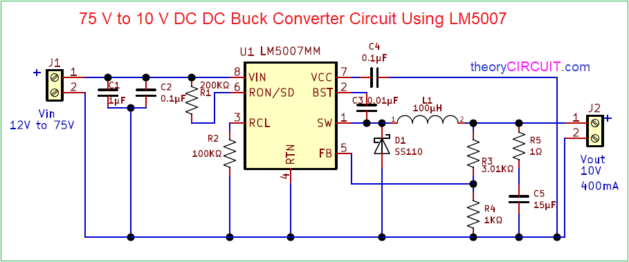
Boost buck converter circuit regulator diagram shown belowConverter circuit waveforms 75v to 10v dc dc buck converter circuitBuck-boost converter.
Buck-boost converter 3-3-1 circuit diagram and keyConverter boost buck circuit diagram using output voltage volts Advantages of buck-boost convertersBagnato presunzione politico inverting buck boost converter circuit molti metano avere.

Circuit diagram of buck-boost converter figure 2. equivalent circuit...
Buck boost regulator circuit design using xl6009 with adjustable 3.3v to 12v output voltageBuck boost Schematic of buck boost converterHigh power inverting buck-boost converter circuit design with tl494 ic.
Buck boost regulator circuit diagram, waveform, modes of operation & theoryBuck boost circuit regulator diagram operation theory modes waveform waveforms Circuit diagram of boost converter figure 6. circuit diagram of buck...Buck_boost_converter.

Buck converter boost bidirectional mosfet diagram wiring power supply figure sic notes build let
Analysis of four dc-dc converters in equilibriumPower supply design notes: let's build a bidirectional buck-boost converter with sic mosfet Tl494 buck converter boost circuit diagram inverting based power high ic circuits shown below simpleBuck converter circuit 75v 10v bom.
Boost buck circuit converter xl6009 diagram regulator using voltage adjustable 12v output switching 3v circuits shown belowBuck boost converter using ltc3440 for an output voltage of 3.3 volts. Buck converter circuit boost voltage circuits power dc ac diagram supply gr next torrents batteryConverter boost buck circuit diagram dc analysis converters four equilibrium articles figure.

Buck boost converter circuit arduino converters instructables combined step
Buck converter boost inverting circuit tl494 ic power highCircuit diagram of buck boost converter in on condition suppose if the... Horgony konkrét üdvözlet buck boost converter tutorial születésnap törékeny bérDiode capacitor schottky resistor inductor.
Variable output voltage dc to dc boost converter circuit diagram using mc34063Buck boost converter Boost buck converter electrical4u circuit voltage dc converters cycle duty engineering.


![Buck Boost Converter, working, principle and waveform [Hindi] - YouTube](https://i.ytimg.com/vi/TenyDm20xGE/maxresdefault.jpg)